3.1 KiB
| tags | |||
|---|---|---|---|
|
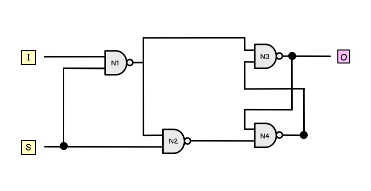
Creating memory with NAND gates
The logic circuit below demonstrates how memory can be created using NAND gates. A single bit is stored in memory.
 Interactive version of circuit:
Components
- I is where we input the bit that we want to remember.
- O is the output of the remembered bit
- S is an input that tells these gates when to set the memory.
- A, B, C are internal wires that represent the individual bit values which channel into each gate
State changes
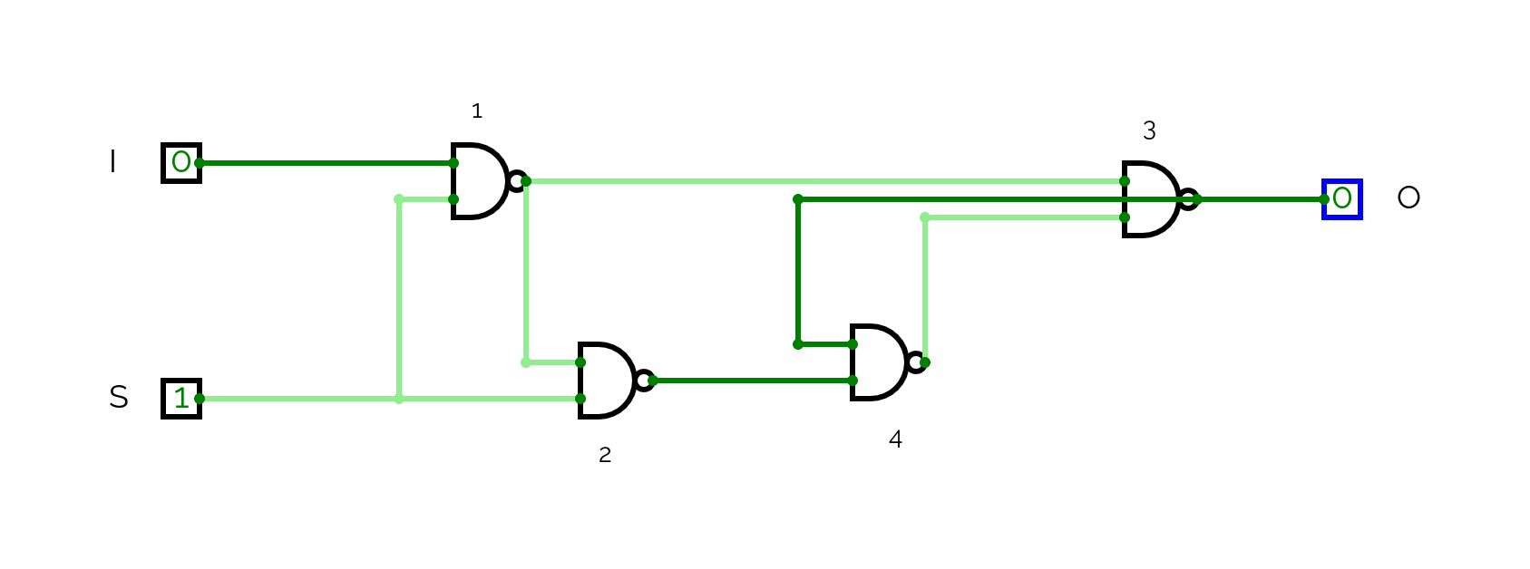
First state: S ON, I OFF
- Start with S
ONand IOFF. - Given the logic of NAND, A will be on.
- This means Gate 2 is receiving
ONfrom A andONfrom S thereforeBisOFF - Moving to Gate 4 it is receiving
OFFfrom B and it's other input is not activated so is therefore alsoOFF. Consequently C isON Cis fed as the second input into Gate 3, thus we have both inputs (A and C) asON, therefore the output will make OOFF
Upshot: With S
ON, output is the same as input
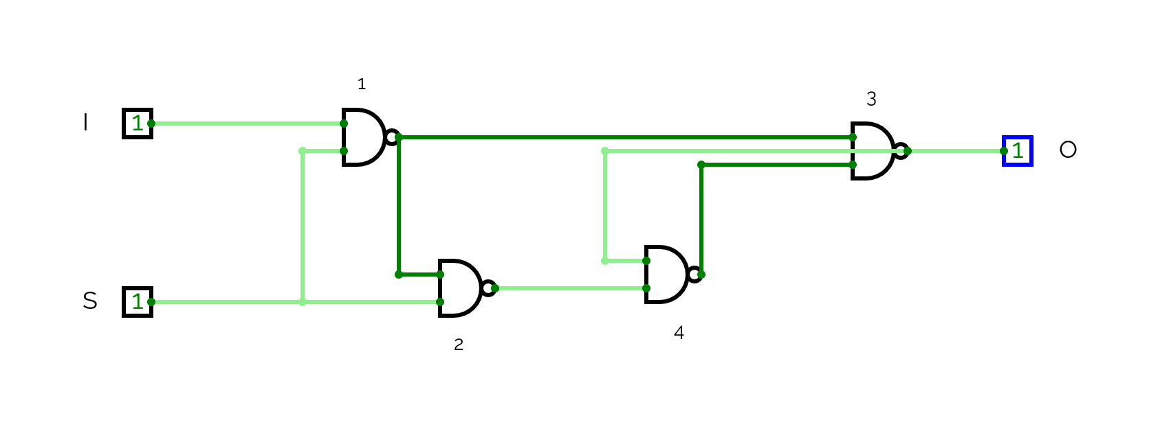
Second state: both S and I ON
- With S and I both on, Gate A will be
OFF - Gate 2 is receiving
OFFfrom A andONfrom S therefore B isON - A feeds into Gate 2 which is receiving
ONfrom S, therefore the output (B) will beON - A feeds into Gate 3 and the other input is
OFF, therefore Gate 3 is outputtingON. Thus O isON - O feeds back to Gate 4 which is receiving
ONfrom B thus we have twoONinputs going into Gate 4, turning C off - This means the two inputs going into Gate 3 are both
OFF, keeping OON
Upshot: With S on, the output is again the same as the input
So far we have seen that when S is
ONyou can change I on and off and O will change with it.
Memory
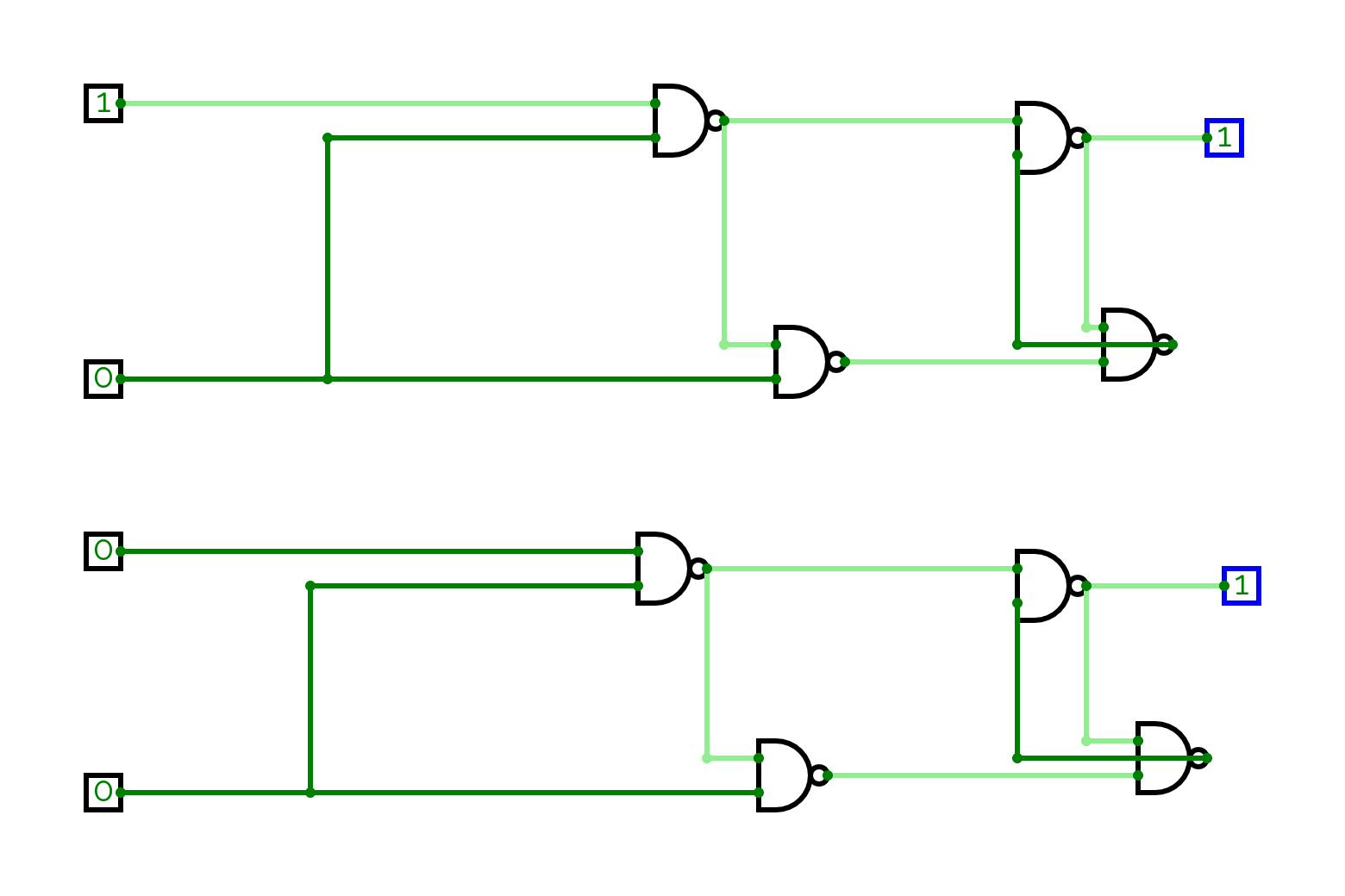
When S is ON, O will mirror whatever state I is in. However if you
turn S OFF, O will remain in whatever state it was when S was
turned OFF. You can toggle I as much as you like, O will remain in its
previous state. Hence creating a memory store of the past value of I.
The specific reason for this is that, if S is OFF, both A and B
are ON since at Gate 1: ON (I) + OFF (S) = ON and OFF (I) + OFF (S) = OFF
and at Gate 2: OFF (Gate 1) + OFF (S) = OFF
This is illustrated in the diagram below. The space occupied by A and B remains on (note it is illuminated) regardless of the state of I.