---
title: "Building my homelab: installing CAT6A"
slug: /starting-my-homelab-installing-cat6A/
date: 2026-01-02
tags: ["projects", "self-hosting"]
---
Now that I am no longer renting, I am in a position to build my own "homelab".
For those not in the know, a homelab is a computational environment in your home
that you can use to run your own servers, networking equipment and services.
Here is an example cribbed from Reddit:

I already maintain a remote virtual private server which I have described in
previous blog posts, but I have long wanted to maintain my own physical
environment so I can learn more about system administration, run domestic
automations and basically have fun.
I've been laying the groundwork for this already. When I redecorated my office
in the summer I deliberately stripped-out a recessed cupboard so that I could
use the space for the homelab. Similarly, the
[router cabinet](https://systemsobscure.blog/posts/creating-a-router-cabinet)
project was designed to eventually interface with the lab.
The main impediment, until now, was the lack of a direct Ethernet connection
from the router in the lounge to the office. I knew that ultimately I would have
to address this and had been putting it off.
I decided to use the Christmas break to do the necessary work. The most
efficient and least-obstrusive way to get wired access to the router was run
Ethernet from the lounge to the office via the loftspace.
I bought 25m of CAT6A (which allows for speeds of up to 10Gb/s) along with:
- keystone jacks and surface-mount boxes for the terminal points
- rounded conduit and fixtures
- flexible trunking (for bends)
Rather than use a single connection from the router to the homelab link switch,
the more professional approach is to have a mounted outlet at each termination
point and connect from these to the devices via patch cable.
The first task was the scariest: drilling into the loft. I was careful to check
for surrounding piping and mains cabling but it was still a bit nerve-racking.
Luckily the holes went into the ceiling board fine. I inserted rubber grommits
to stop the holes wearing away when the cable was fed through. I also made use
of electrician's 'fishing rods' to feed the cable into the loft, through the
ceiling and insulation.
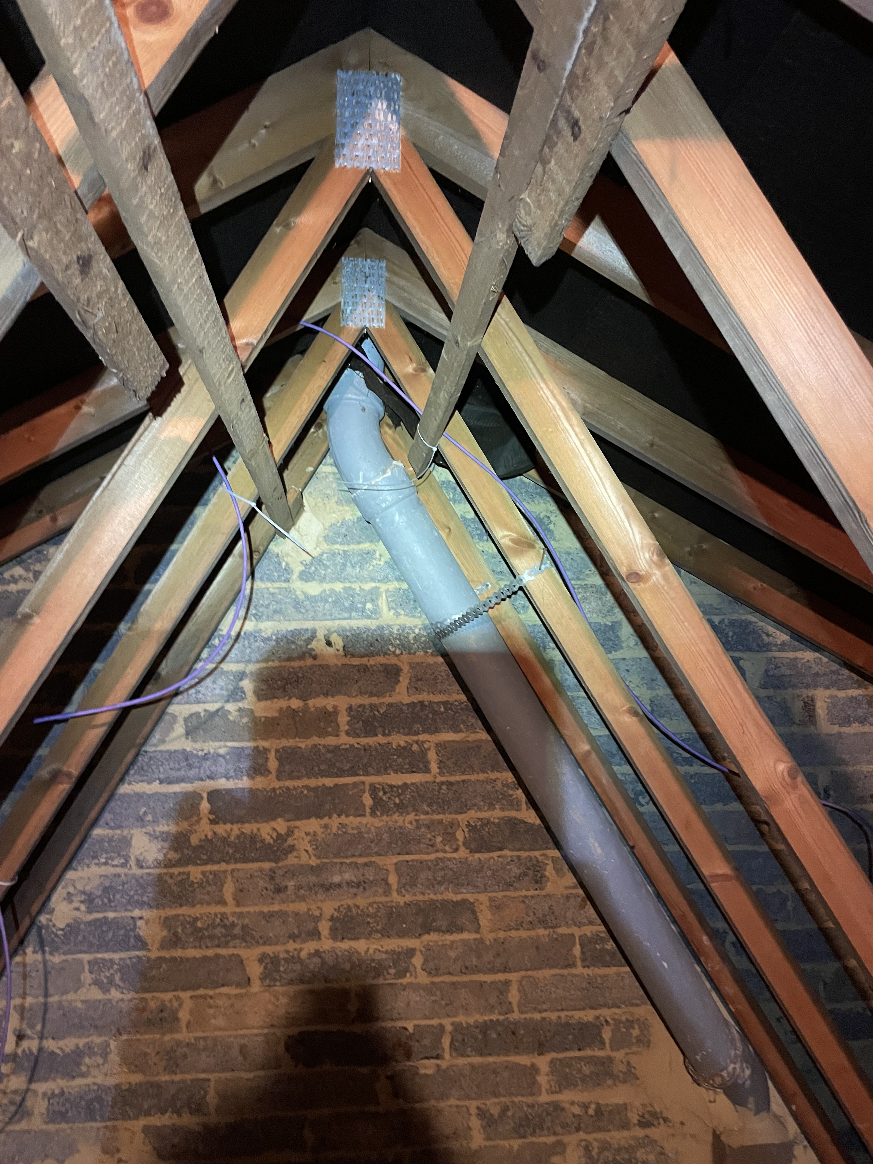

During testing and installation, I just used cable ties to fix the CAT6A to the
loft beams when channeling the cable between the two outlets. I'll go back later
(probably when I get round to boarding it properly) and use cable tacks as they
are neater.
How things look in the loft
The work in the loft was the most arduous. I had to lie accross wobbly planks
and handle fiberglass insulation. Even with gloves and long-sleeves this was
really itchy.
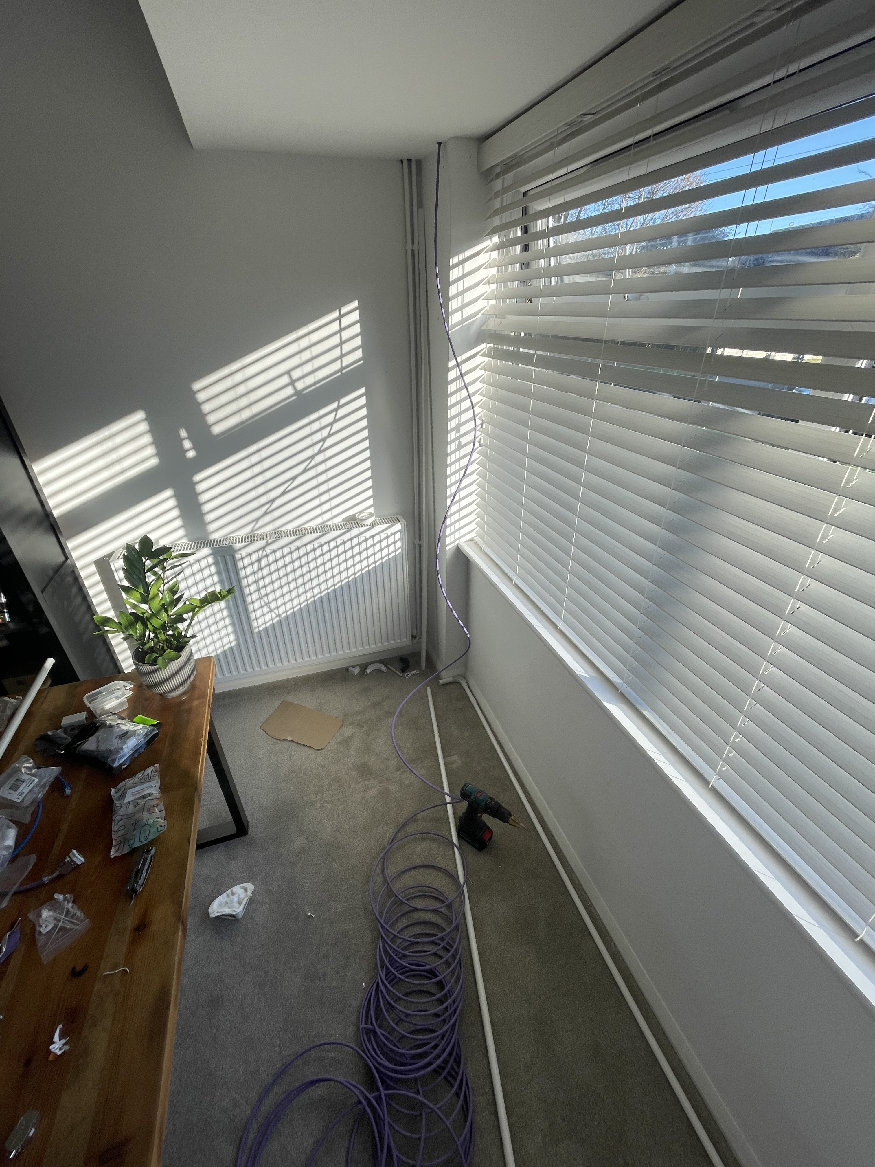
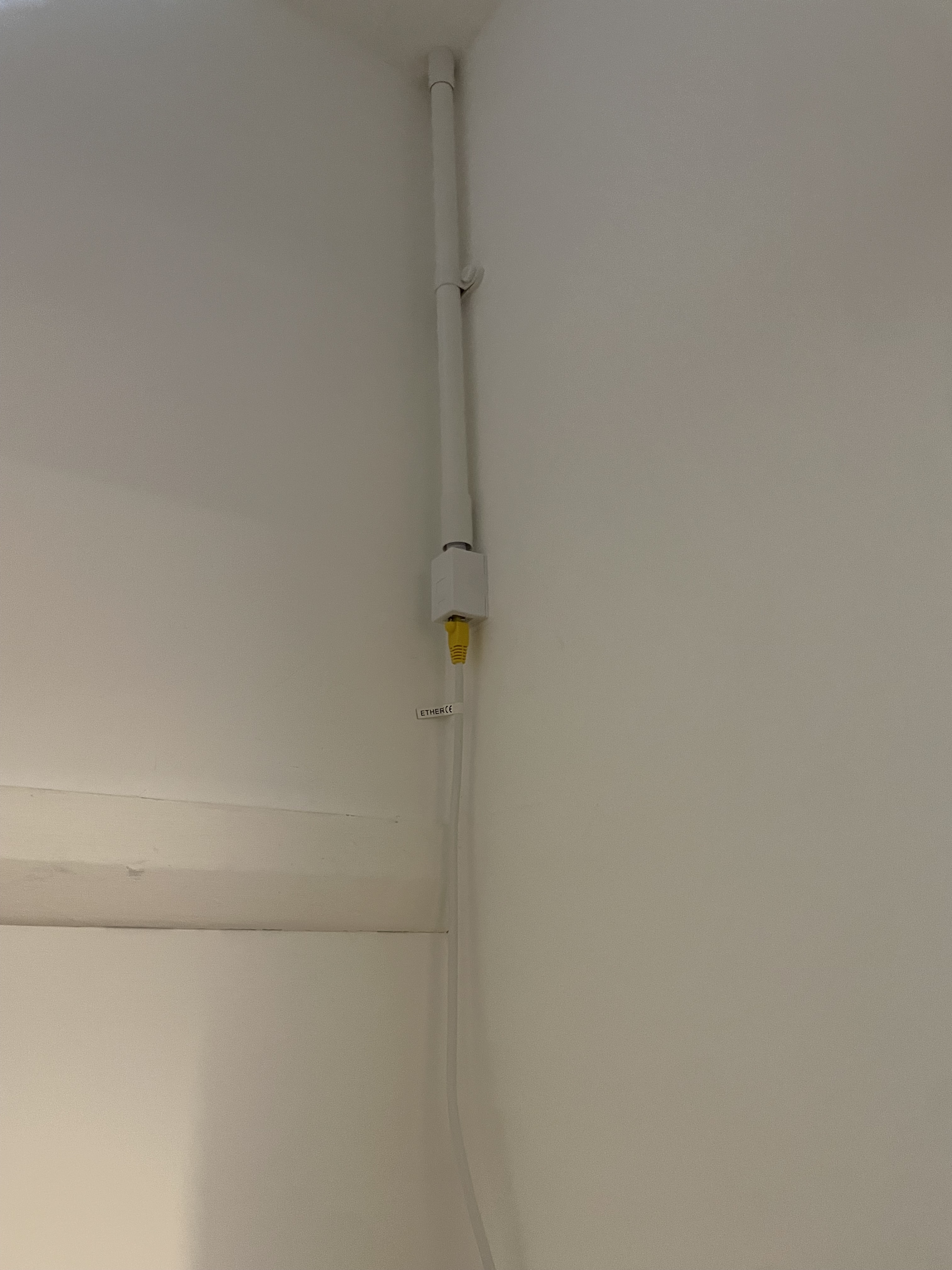
Once the cable had been laid, the next task was to try and hide it as much as
possible in the downstairs rooms. I originally purchased standard flat conduit
for this purpose but I realised that the 90 degree bends required would likely
damage the cable over time. So I had a rethink and used fully-round conduit with
more forgiving inspection bends. For the sharpest turn I just used bendable
trunking and accepted that function would have to trump aesthetics.
Conduit and trunking in lounge
The main learning curve was installing the keystone jacks. By using jacks I was
able to avoid crimping the terminal points of the cable. This is quite a skill
and as it was my first attempt, I knew I would probably mess it up and waste the
cable in the process.
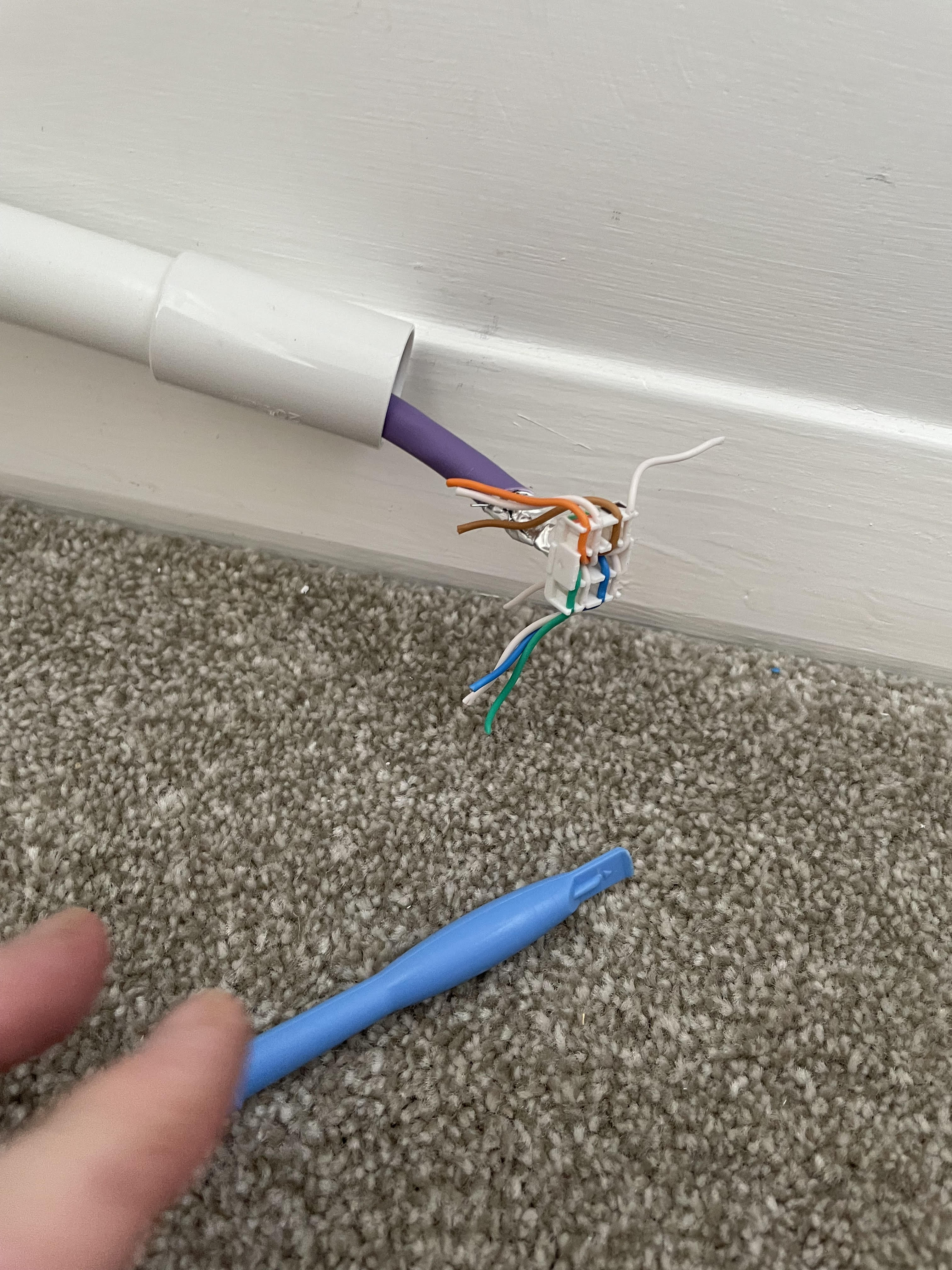
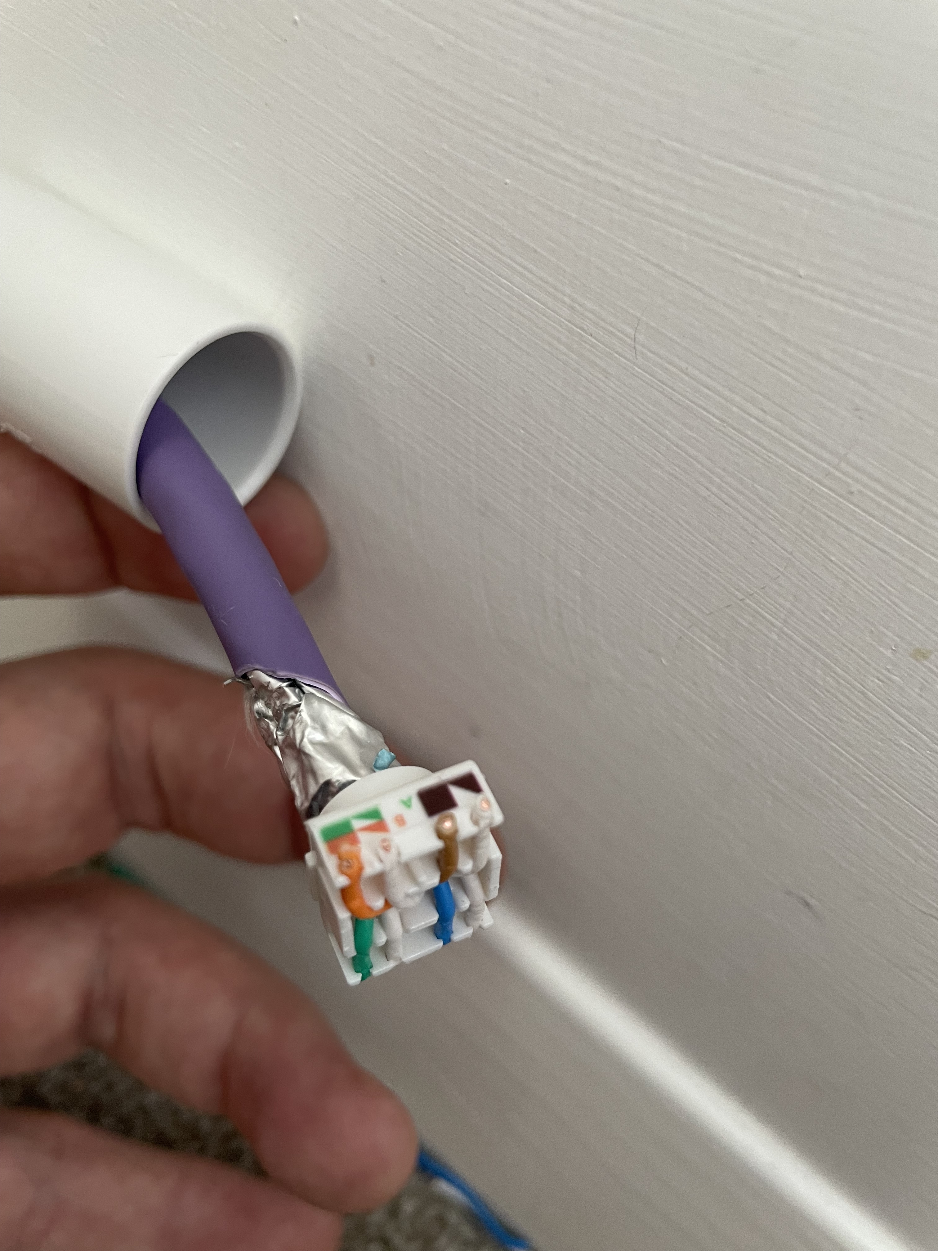
To use the jack, you strip the sheathing back and feed the four paired wires
into a fixing plate which is then clamped down with pliers. The clamping cuts
the wires for you and ensures the copper makes contact with the pins. I
deliberately chose jacks with zinc shielding which earths the cable when it is
in contact with the metallic wrappers of the individual wires.
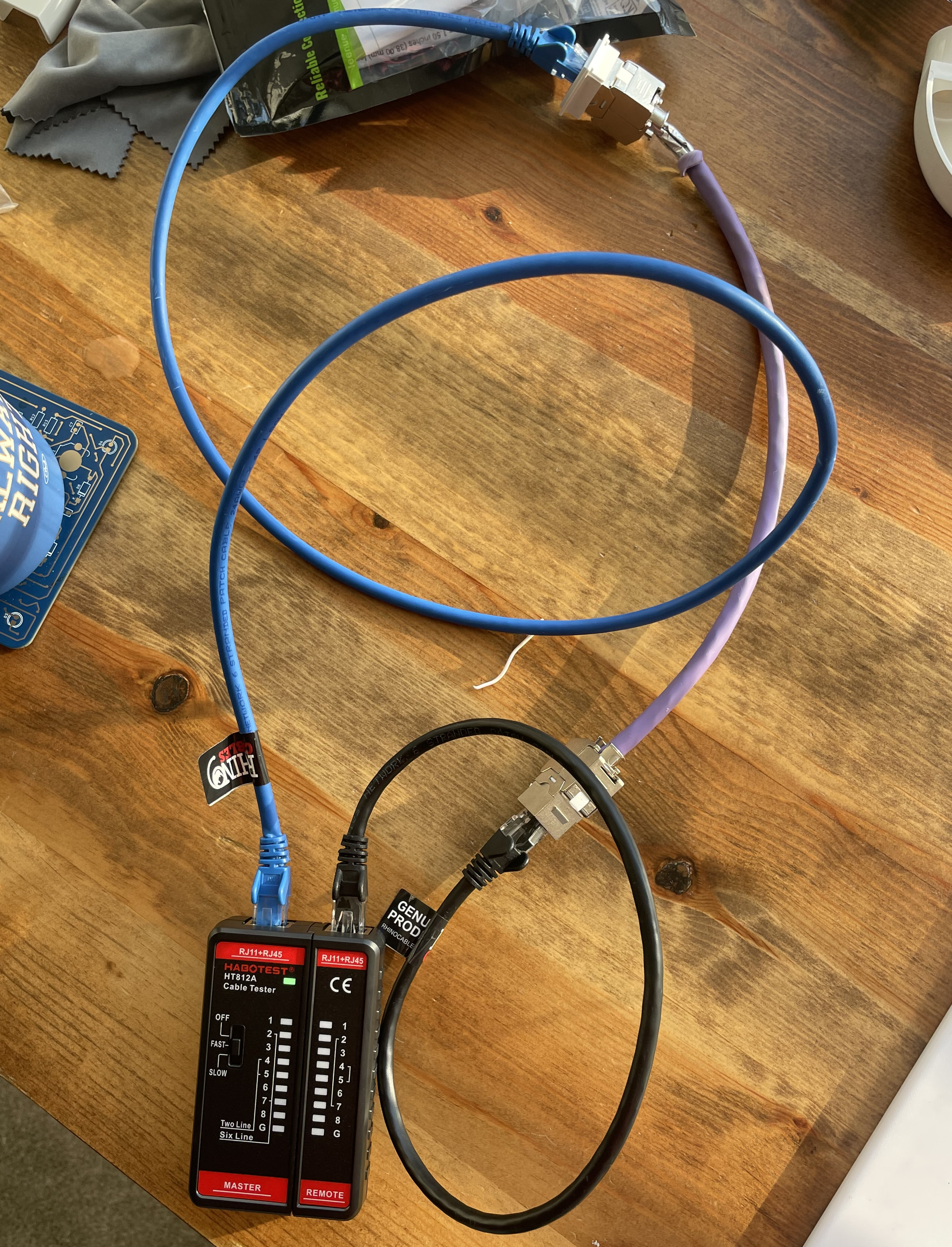
Before doing it for real I did several practice runs with cable offcuts. I also
bought a basic RJ45 cable tester so that if I had made a mistake, I would know
about it early on in the process.

This paid off and by the time I did it for real, it was pretty straightforward.
It was really gratifying at the end of the process to patch in from the office
and record 1GB/s as a result of my hard work.
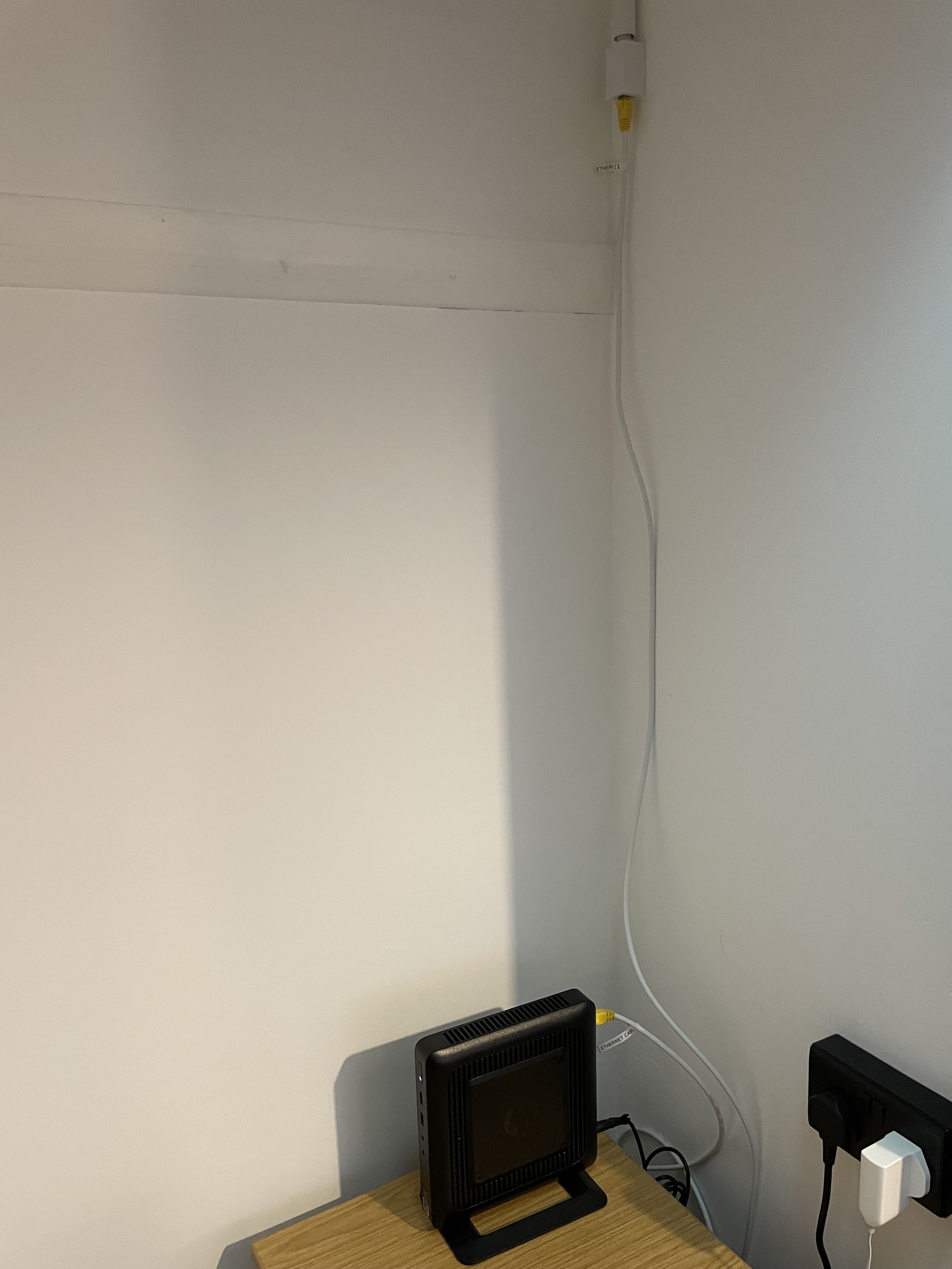
Right now I just have my HPT520 Thin-Client running on the new cable. This runs
Pihole and an MQTT server. The next step will be to get a rack and switch unit
and start building the actual lab!